
This is the second part of the online course dedicated to interactive maps.
This is a tutorial in three parts:
- Part 1: Interactive Map Shader: Vertex Displacement
- Part 2: Interactive Map Shader: Scrolling Effect
- Part 3: Interactive Map Shader: Terrain Shading
A link to download the Unity package for this tutorial can be found at the end of this article.
In the previous lecture of this online course, we created a vertex function which extrudes the vertices of a mesh upwards. The intensity of the effect is controlled by a texture, the height map, so that brighter pixels are raised more, compared to darker ones.
void vert(inout appdata_base v)
{
    float3 normal = float3(0, 1, 0);

    fixed height = tex2Dlod(_HeightMap, float4(v.texcoord.xy, 0, 0)).r;
    vertex.xyz += normal * height * _Amount;
}


What we have done so far works relatively well. Before we continue, let’s also factor the code necessary to calculate the new vertex height into its own function, called getVertex:
float4 getVertex(float4 vertex, float2 texcoord)
{
    float3 normal = float3(0, 1, 0);

    fixed height = tex2Dlod(_HeightMap, float4(texcoord, 0, 0)).r;
    vertex.xyz += normal * height * _Amount;
    return vertex;
}
Now, the entire vert function becomes:
void vert(inout appdata_base v)
{
    vertex = getVertex(v.vertex, v.texcoord.xy);
}
The reason why we do this is that in the next sections we will need to calculate the height of multiple points. Having this functionality in its own separate function makes the code much easier.
Calculating UV Coordinates
This, however, opens up another issue. The getVertex function depends not only on the current vertex position (v.vertex), but also on its UV coordinates (v.texcoord).
When we want to calculate the height displacement of the vertex that the vert function is currently processing, both pieces of information are available in the appdata_base structure. However, what happens if we have to sample the position of a nearby point? In that case, we might know its xyz position in model space, but we have no access to its UV coordinates.
This means that the current solution is able to calculate the height displacement for the current vertex only. Such limitation would prevent us from moving forward, so we need to find a solution.
The most simple one is to find a way to calculate the UV coordinates of the 3D object, knowing its vertex position. Technically speaking, this is a very complex problem and there are several techniques that attempt to solve it (the triplanar projection being one of the most popular). In this specific case, however, we do not need to map UV to any geometry. If we assume that our shader is only ever going to be used on a flat mesh, then the problem becomes trivial.
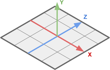
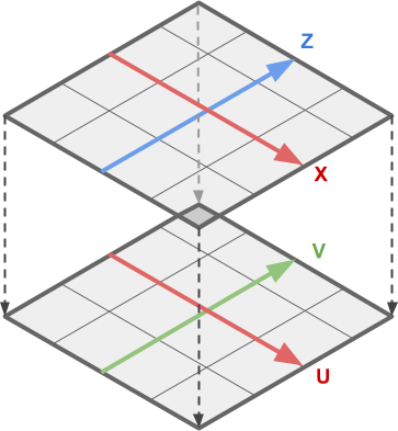
What makes calculating UV coordinates (below, right) from vertex positions (below, left) possible is the fact that, on a flat mesh such as a plane, they are both mapped linearly.
 |
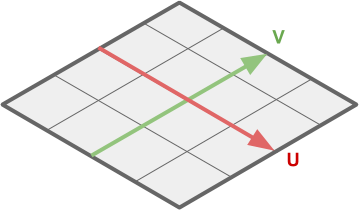 |
This means that, in order to solve our problem, we need to remap the XZ components of the vertex position onto their respective UV coordinates.
This is known as linear interpolation, and is a topic that has been covered extensively on this website (for instance: The Secrets Of Colour Interpolation).
Most UV values range from  to
to  ; conversely, the coordinates of each vertex are potentially unbound. Mathematically speaking, the only things that we need to perform linea remapping of XZ onto UV are their extreme values:
 ,
, 
 ,
, 
 ,
, 
 ,
, 
which can be seen below:
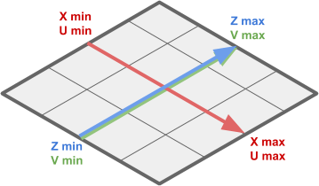
These values changes depending on the mesh used. On a Unity plane, the UV coordinates range from to , while the vertex coordinates range from  to
to  .
.
The equations that remap XZ onto UV are:
(1) 
Their derivation, however, is fairly simple. Let’s focus on  only for this derivation. We have two ranges: one goes from to , and the other goes from to . The input is the
  coordinate of the vertex currently being processed, and the output will be the coordinate used to sample the texture.
The properties that we want to preserve, is the proportionality between and its interval, and  and its interval. For instance, if is at 25% of its range, then will have to be at 25% its range as well.
We can see all of this in the following diagram:

From which we can derive that the proportion the red segment makes with respect to the light red one, has to be the same to the one that the blue segment makes with respect to the light blue one:
(2) 
Now, we can rearrange the equation above to extract :

which is exactly the one presented earlier, (1).
These equations can be implemented like this:
float2 _VertexMin;
float2 _VertexMax;
float2 _UVMin;
float2 _UVMax;

float2 vertexToUV(float4 vertex)
{
    return
        (vertex.xz - _VertexMin) / (_VertexMax - _VertexMin)
        * (_UVMax - _UVMin) + _UVMin;
}
Now, we can invoke getVertex without the need to pass v.texcoord to it:
float4 getVertex(float4 vertex)
{
    float3 normal = float3(0, 1, 0);
    float2 texcoord = vertexToUV(vertex);

    fixed height = tex2Dlod(_HeightMap, float4(texcoord, 0, 0)).r;
    vertex.xyz += normal * height * _Amount;
    return vertex;
}
And the entire vert function becomes:
void vert(inout appdata_base v)
{
    v.vertex = getVertex(v.vertex);
}
⭐ Suggested Unity Assets ⭐
The Scrolling Effect
With the code that we have written so far, the entire map now appears on the mesh. If we want to improve this, we need to make some changes.
Let’s formalise this a bit more. First of all, we might want to zoom in on a specific part of the map, rather than seeing it in its entirety.
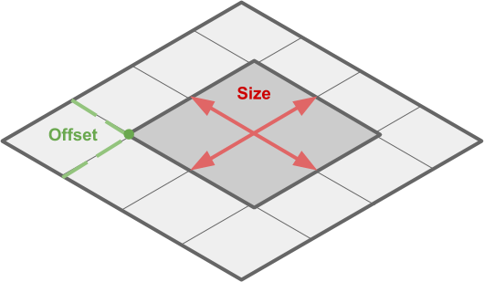
We can define this region with two pieces of information: how large it is (_CropSize) and where it is on the map (_CropOffset), measured in vertex space (from _VertexMin to _VertexMax).
// Cropping
float2 _CropSize;
float2 _CropOffset;
Once we have these two values, we can use linear interpolation once again to make sure that getVertex is not called on the actual vertex position of the 3D model, but on a rescaled, translated point.

With the relative code:
void vert(inout appdata_base v)
{
    float2 croppedMin = _CropOffset;
    float2 croppedMax = croppedMin + _CropSize;

    // v.vertex.xz: [_VertexMin, _VertexMax]
    // cropped.xz : [croppedMin, croppedMax]
    float4 cropped = v.vertex;
    cropped.xz = (v.vertex.xz - _VertexMin) / (_VertexMax - _VertexMin)
        * (croppedMax - croppedMin) + croppedMin;

    v.vertex.y = getVertex(cropped);
}
If we want this to actually scroll, then we simply have to update _CropOffset via a script. This moves the cropped area, de-facto scrolling over the landscape.
public class MoveMap : MonoBehaviour
{
    public Material Material;
    public Vector2 Speed;
    public Vector2 Offset;

    private int CropOffsetID;

    void Start ()
    {
        CropOffsetID = Shader.PropertyToID("_CropOffset");
    }

    void Update ()
    {
        Material.SetVector(CropOffsetID, Speed * Time.time + Offset);
    }
}
In order for this to work, is very important that all the textures used have their Wrap Mode mode set to Repeat. If not, you will not be able to loop around the texture.
For a zoom-in/zoom-out effect, you can simply chance the _CropSize.
What’s Next…
One important aspect that we have overlooked, is the shading. The geometry appears, in fact, dull and flat. You can see how the model looks now (left) and how it should actually look (right).
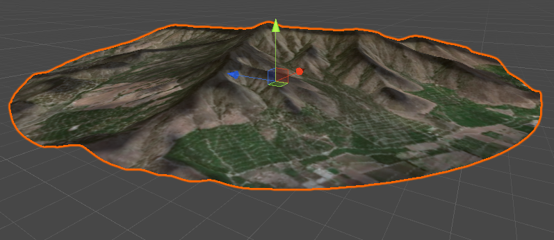
We will fix this in the third, and final, part of this online course on interactive map shaders.
- Part 1: Interactive Map Shader: Vertex Displacement
- Part 2: Interactive Map Shader: Scrolling Effect
- Part 3: Interactive Map Shader: Terain Shading
Unity Package Download
Become a Patron!
The full package for this tutorial is available on Patreon, and it includes all the assets necessary to reproduce the technique here presented.
💖 Support this blog
This website exists thanks to the contribution of patrons on Patreon. If you think these posts have either helped or inspired you, please consider supporting this blog.
📧 Stay updated
You will be notified when a new tutorial is released!
📝 Licensing
You are free to use, adapt and build upon this tutorial for your own projects (even commercially) as long as you credit me.
You are not allowed to redistribute the content of this tutorial on other platforms, especially the parts that are only available on Patreon.
If the knowledge you have gained had a significant impact on your project, a mention in the credit would be very appreciated. ❤️🧔🏻
Webmentions
[…] Part 2: Interactive Map Shader: Scrolling Effect […]
[…] Part 2: Interactive Map Shader: Scrolling Effect […]