

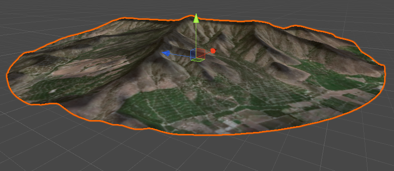
This is the third part of the online course dedicated to interactive maps.
This is a tutorial in three parts:
- Part 1: Interactive Map Shader: Vertex Displacement
- Part 2: Interactive Map Shader: Scrolling Effect
- Part 3: Interactive Map Shader: Terain Shading
A link to download the Unity package for this tutorial can be found at the end of this article.
Flat Shading
All the code written so far works really well, but has a big problem. There is something wrong with the shading of the model. The surface is indeed curved, but it reacting to light as if it was flat.
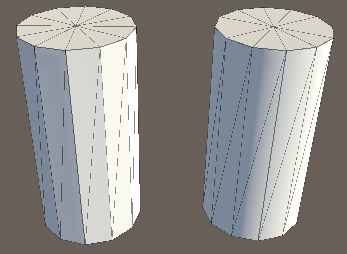
This can be seen very clearly in the images below. On the left, there is our current shader; on the right, one that actually works.

Fixing that problem will be the real challenge of this shader. But first, we need to understand what went wrong.
The operation of normal extrusion that we have performed has altered the overall geometry of the flat plane that was originally used. However, Unity we have only changed the position of the vertices, not their normal directions. The normal direction of a vertex is, like the name suggests, a vector of length one (a direction) which points away from the surface. The reason why normals are so important is that they play a crucial role in the shading of a 3D model. They are used by all surface shaders to calculate how light should reflect on each triangle of the 3D model. Normally, this is used to enhance the three-dimensionality of a model, for instance by forcing light to reflect on a flat surface in the same way it would on a curved one. That trick is often used to make low poly surfaces appear more smooth than they actually are (below).
In this case, however, the opposite is happening. Our geometry is curved and smooth, but since all of the normals are pointing up, light will reflect on the model as if it was flat (below):

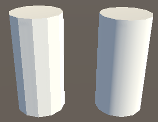
You can read more about the role normals play in shading an object on Normal Mapping (Bump Mapping), where the exact two same cylinders appear very different, despite having the same 3D model, because of the way normals are calculated on their vertices (below).
 |
 |
Unfortunately, neither Unity nor the shader language offer any built-in solution to automatically recalculate the normals. That means that we need to adjust them manually, based on the local geometry of the 3D model.
Calculating Normals
The only way to fix our lighting issue is to manually calculate the normals, based on the surface geometry. A similar challenge has been discussed in Vertex Displacement – Melting Shader Part 1, where it has been used to simulate the melting of 3D models in a game called Cone Wars.
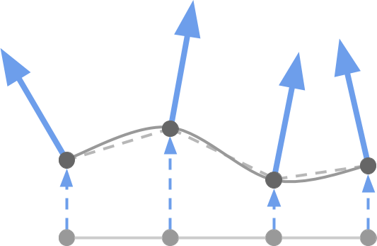
Although the final code needs to work on 3D coordinates, let’s restrict the problem to only two dimensions for now. Let’s imagine that we want to calculate the normal direction associated with a point of a 2D curve (diagram below, the large blue arrow).
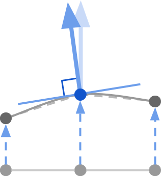
Geometrically speaking, the normal direction (the large blue arrow) is a vector perpendicular to the tangent line that passes through the point of interest (the thin blue line). Intuitively, you can think about the tangent line as a line that is sitting along the curvature of the model. The tangent vector is, in a nutshell, a unit vector (a vector of length one) which lays flat on the tangent line.
This means that calculating the normal requires two steps: firstly, we have to find the line that is tangent to our point; secondly we calculate a vector perpendicular to it (which is indeed the normal direction we want).
⭐ Suggested Unity Assets ⭐
Calculating Tangents
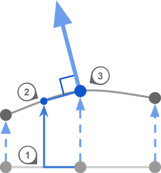
To get the normal, we first need to get the tangent. That can be approximated by sampling a nearby point, and using it to build a segment around our vertex. The smaller the segment, the more precise we will be.
Three steps are needed:
- Step 1. Move along the flat surface by a small amount
- Step 2. Calculate the height of the new point
- Step 3. Use the height of the current point to calculate the tangent
which can be seen in the image below:
In order for this to work, we need to calculate the heights of two points, not just one. Luckily, this is something that we already know how to do. In the previous part of this course, Interactive Map Shader #2: Scrolling Effect, we have created a function that can sample the height of the landscape, given a point on the mesh. We called it:getVertxex.
The idea is to get new vertex value at the current point, then two more points. One along the tangent, one along the bitangent. Using them you can get the normal. If the original mesh that is used to create this effect is flat (it is, in this case), so we don’t need to access v.normal, but we can simply use float3(0, 0, 1) and float3(1, 0, 0) for the tangent and bitangent, respectively. If we wanted to do the exact same thing but on a sphere, for instance, finding two suitable points to calculate the tangent and bitangent would have been much trickier.
The Cross Product
Once we have two suitable tangent and bitangent vectors, we can calculate the normal using an operation known as the cross product. There are many ways to define and explain what the cross product is, and what it does.
The cross product takes two vectors, and returns a new one. If the two original vectors are unit vectors (have length equal to one), and if they are 90 degrees apart, then the resulting vector is 90 degrees apart from both.
This might seem a bit confusing at first, but you can visualise it like this: the cross product of two axes, produces the third one. So  , but also
  , and so on.
If we take a small enough step (offset, in the code), then both the tangent and bitangent vectors should be 90 degrees apart. Together with the normal vector, they form three orthogonal axes oriented along the surface of the model.
With this knowledge, we can now write the necessary code to calculate and update the normal vector.
void vert(inout appdata_base v)
{
    float3 bitangent = float3(1, 0, 0);
    float3 tangent   = float3(0, 0, 1);

    float offset = 0.01;

    float4 vertexBitangent = getVertex(v.vertex + float4(bitangent * offset, 0) );
    float4 vertex          = getVertex(v.vertex);
    float4 vertexTangent   = getVertex(v.vertex + float4(tangent   * offset, 0) );

    float3 newBitangent = (vertexBitangent - vertex).xyz;
    float3 newTangent   = (vertexTangent   - vertex).xyz;

    v.normal = cross(newTangent, newBitangent);
    v.vertex.y = vertex.y;
}
Putting Everything Together
Now that everything works, we can integrate the scrolling effect back as well.
void vert(inout appdata_base v)
{
    // v.vertex.xz: [_VertexMin, _VertexMax]
    // cropped.xz : [croppedMin, croppedMax]
    float2 croppedMin = _CropOffset;
    float2 croppedMax = croppedMin + _CropSize;

    float4 cropped = v.vertex;
    cropped.xz = (v.vertex.xz - _VertexMin) / (_VertexMax - _VertexMin)
        * (croppedMax - croppedMin) + croppedMin;

    float3 bitangent = float3(1, 0, 0);
    float3 normal    = float3(0, 1, 0);
    float3 tangent   = float3(0, 0, 1);

    float offset = 0.01;

    float4 vertexBitangent = getVertex(cropped + float4(bitangent * offset, 0) );
    float4 vertex          = getVertex(cropped);
    float4 vertexTangent   = getVertex(cropped + float4(tangent   * offset, 0) );

    float3 newBitangent = (vertexBitangent - vertex).xyz;
    float3 newTangent   = (vertexTangent   - vertex).xyz;

    v.normal = cross(newTangent, newBitangent);
    v.vertex.y = vertex.y;
    v.texcoord = float4(vertexToUV(cropped), 0,0);
}
This finally completes the effect.
What’s Next…
This was the last part in this online course about interactive map shaders. You can read the other parts below:
- Part 1: Interactive Map Shader: Vertex Displacement
- Part 2: Interactive Map Shader: Scrolling Effect
- Part 3: Interactive Map Shader: Terrain Shading
This tutorial will be the base for other more complex, such as holographic projections and even a copy of the sand table seen in Black Panther.
Unity Package Download
Become a Patron!
The full package for this tutorial is available on Patreon, and it includes all the assets necessary to reproduce the technique here presented.
💖 Support this blog
This website exists thanks to the contribution of patrons on Patreon. If you think these posts have either helped or inspired you, please consider supporting this blog.
📧 Stay updated
You will be notified when a new tutorial is released!
📝 Licensing
You are free to use, adapt and build upon this tutorial for your own projects (even commercially) as long as you credit me.
You are not allowed to redistribute the content of this tutorial on other platforms, especially the parts that are only available on Patreon.
If the knowledge you have gained had a significant impact on your project, a mention in the credit would be very appreciated. ❤️🧔🏻
I like this a lot. An extremely creative program just for us designers. I will make the right comment when I make my first artwork. I hope to be humorous.
not very helpful because you don’t reveal the GetVertex() function…
I do!
Part 2 is literally dedicated to GetVertex()! 😅